
Acute V-Fold Tutorial: Compare Tilt and Mounting Angles
Change the paper and mounting angles separately, then compare two paper samples to understand tilt and opening range.
How to make and compare two acute V-fold samples
Use this lesson's SVG pattern with a 60° paper angle. Follow the route below and the detailed diagrams for fold directions, glue areas and dimensions. Prepare card, scissors, a ruler, a blunt scoring tool and suitable paper adhesive.
Download and check print scale
Download both the C=130° and C=150° SVGs. Print landscape on A4 at 100% or actual size, disable Fit to page and measure the 20 mm calibration line.
Score before cutting
Score the grey spine, red centre crease and green mounting creases. Cut the black outer outlines, keep both tabs and remove the gaps between them. Leave dashed fold lines intact.
Pre-fold from the marked face
Follow the pattern marks: mountain-fold the red and green creases and valley-fold the grey spine. Work the creases gently so the tabs fold behind the wings.
Test the placement without glue
Align the lower end of the centre crease to O and the tabs to the yellow L and R areas, GLUE faces toward the base. Close gently and check that creases move, tabs stay clear of the spine and the sheet fits inside.
Attach one tab, then locate the other
Glue one tab thinly onto its matching area. Glue the second, fold the mechanism into its pre-creased closed position and close the base to help locate it. Keep glue off moving creases and follow the adhesive's pressing and setting instructions.
Make the second sample and compare equal openings
Build the other mounting version with its own parts. After the bonds set as directed, compare both samples closed, at about 90° and fully open, then close again. If either resists, reopen and check mounting angles and page-edge fit separately.
The right-angle lesson introduced the centre crease, mounting creases and glue tabs. We will keep using a simple plain-paper structure to see how paper angles and mounting angles affect the wings.
Run two experiments, changing one kind of angle at a time. Then make two paper samples to compare what you saw on screen.
1. Measure the paper, rather than the photograph
If A, B, C, D and the page opening θ are still unfamiliar, start with the right-angle V-fold lesson.
Unfold the sheet and extend the mounting creases toward O at the lower end of the centre crease. The flat angles between the centre crease and these mounting lines are A and B.
With A=B<90° and matching mounting angles C=D, we have the symmetric acute V-fold discussed here. This lesson uses A=B=60°.
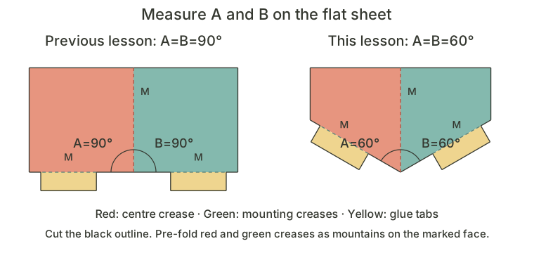
The mounting lines now slope while the upper edge stays straight. Classify the mechanism by its crease angles. A pointed outline or wings that look narrowly opened in a photograph do not establish that it is an acute V-fold.
2. Change only the paper angle
You can also follow the annotated diagrams below.
Keep the base fully open and compare A=B=90° with A=B=60°. Both examples use C=D=130° and the same mounting-edge and centre-crease lengths.
Watch the centre crease. The right-angle example stands perpendicular to the flat base, while the acute example leans toward one end of the spine. The paper angle changed; the book remains fully open and the camera stays in place.
Move the page opening to roughly 90° and repeat the comparison. The wings change pose during motion, so record the paper angle, mounting angle and current page opening together.
3. Change only the mounting angle
Keep the same A=B=60° sheet and change its mounting angles from C=D=130° to 150°. The wings, tabs and crease pattern all stay the same.
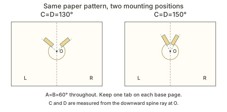
You can also follow the annotated diagrams below.
With the base fully open and the camera unchanged, the 150° example has a more upright centre crease than the 130° example. Only the direction in which the sheet attaches to the base has changed.
Measure C and D from the downward spine ray at O. The 150° mounting lines sit closer to the upward spine direction, yet their readings from the downward ray are larger. A different starting ray can reverse what someone means by increasing or decreasing an angle.
This comparison concerns these two valid mounting arrangements. Record the actual A, C and page opening rather than treating increasing C as a universal way to make every mounting direction more upright.
4. Why can some acute V-folds only open partway?
Select “C=D=80° · limited” in the mounting experiment. The paper angle remains 60° and the structure still moves through part of the range, but this model stops at roughly 123° rather than showing an unreachable 180° pose.
This value comes from the lesson’s ideal geometric model. A structure that moves and rises does not necessarily open all the way to 180°. If a physical sample resists, reopen and inspect it. Bending the paper under force does not establish correct mounting.
For the symmetric, non-degenerate acute configuration discussed here, a fully flat base requires C<A or C>180°−A, with A=B and C=D.
| Paper angle | Mounting angle | Condition at full opening |
|---|---|---|
| A=60° | C=130° | Greater than 120°; within the range used here. |
| A=60° | C=150° | Also greater than 120°. |
| A=60° | C=80° | Neither below 60° nor above 120°; only part of the motion is reachable. |
The equalities are degenerate boundaries and are not used for this exercise. Angle conditions do not replace checks for tab clearance, fitting inside the page or physical test folds. Make the 130° and 150° versions first.
5. Make two samples to compare the mounting angles
Download the C=D=130° practice pattern and the C=D=150° practice pattern. Their pop-up sheets match; their base glue positions differ.
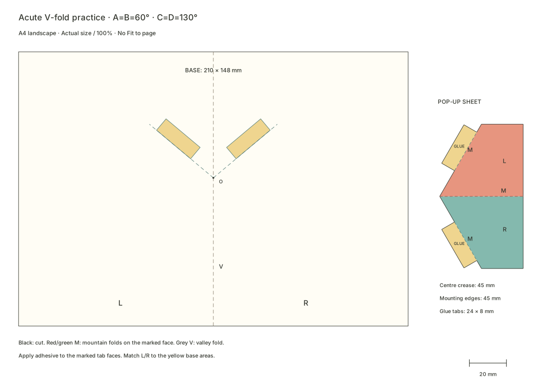
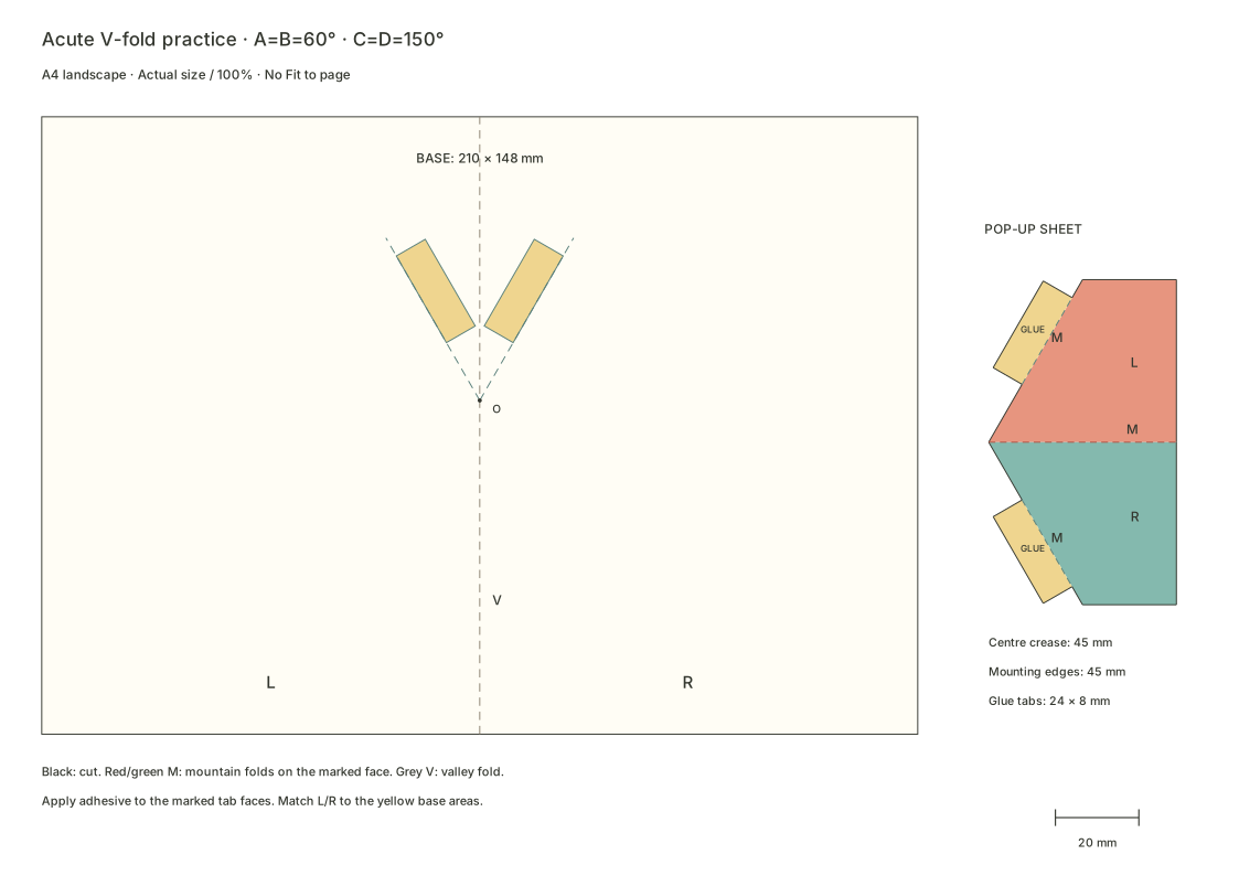
Print landscape on A4 at actual size or 100%, with Fit to page disabled. Check the 20 mm calibration line first. Each base is 210×148 mm. The centre crease and both mounting edges are 45 mm long, and each tab is 24×8 mm. The tabs stop short of O.
1. Cut two sets of parts
Lightly score the dashed lines, then cut the black outer outlines. Red is the centre crease, green marks the mounting creases and grey marks the base spine. Keep both tabs and remove the surrounding gaps. Do not cut the dashed lines.
Compare the two pop-up sheets to confirm matching creases and tabs. Set each beside its base and check whether the base title says 130° or 150°.
2. Pre-fold and position without glue
From the marked face, mountain-fold the red and green creases and valley-fold the grey spine. Align the lower end of the centre crease with O and match the tabs to the yellow L and R areas. The tab faces marked GLUE face the base.
Fold the wings together and gently close the base. Check that each tab stays on its own page, the creases move and the sheet fits inside. The tabs do not need to meet at O.
3. Assemble at the matching glue positions
Glue one tab with a thin coat. Apply adhesive to the other, bring the mechanism into its pre-folded closed position and close the base to help locate it. Follow the adhesive instructions for pressing and setting, keeping glue within the tab areas.
Use the second set for the other mounting angle. Separate samples allow a side-by-side comparison at equal page openings while preserving the first assembly.
4. Let the bonds set, then compare equal states
Open both samples fully and compare their centre creases. Then open both to roughly 90° and observe how they fold away. Record the differences and slowly close and reopen them.
Check that both samples have clear creases and secure tabs. If either catches, locate the problem before adjusting it.
6. Classify the creases even when the silhouette changes
Once a basic sample opens smoothly, trim a small upper corner from one wing while preserving the centre crease, mounting creases and tabs. Repeat the same motion. Distinguish changes to the silhouette from changes to the creases that govern movement.
Finished works may suggest pointed forms, bodies or mouths. A pointed upper edge alone does not identify a pointed V-fold; check the creases and connections as well. First understand the ordinary acute configuration. Pointed forms, counter-folds and combinations can follow as separate topics.
7. Restore the comparison conditions before troubleshooting
| What happens | What to check first |
|---|---|
| The mounting change seems to make no difference | Compare the same A, page opening and camera direction. |
| One wing sits higher than the other | Check matching A/B and C/D, and look for a skewed tab. |
| The structure pulls partway through opening | Check the mounting range and glue on moving creases. Stop forcing it. |
| Tabs overlap or meet the spine | Check the pattern’s clearances and matching base glue areas. |
| It opens but extends beyond the closed page | Check sheet size, O position and folding direction separately from the open composition. |
To compare in the workbench, create a project from the basic V-fold element, place it on the spine and select it. Set the paper angle A to 60° and mounting angle C to 130°, then open the pages to 180°. Keep the camera fixed and change only C to 150°. The default triangular wings demonstrate the same angle relationships; use the downloads for this lesson’s straight upper edge.
Finally, identify the angle that makes this an acute V-fold. Explain why two A=60° samples can lean differently, and why movement alone does not prove a full opening range. The next lesson will apply the same observation method to obtuse V-folds.
Questions you may have
Why can acute V-folds lean differently?
Acute describes paper angles A and B below 90°; mounting angles also affect the lean. This lesson holds A=B=60° and compares C=D=130° with 150°. Keep the page opening and viewing direction the same when comparing.
Can every acute V-fold open to 180°?
The acute classification alone does not establish that. The A=60°, C=80° example shows limited motion. Build the supplied 130° and 150° mounting versions first, and check motion range, tab clearance and closed-page fit separately.
How should I compare the two acute V-fold patterns?
The mechanism sheets match while the base glue areas differ. Print landscape on A4 at actual size and check the 20 mm line. Mount each on its own base. After the bonds set, compare the centre-crease lean at equal page openings, then close both samples.